How this works
By default, the PMS interface uses com port 0 and the Call Accounting server will use com port 1 to communicate with the PMS system. You'll find these two ports labeled CAS and PMS on the Comxchange controller. The ComXchange PMS interface will always be a client to the PMS so the ComXchange will initiate the communication. In its default configuration the ComXchange will send an ENQ to the PMS and will expect to receive an ACK back from the PMS System. This Acknowledgement is the first sign the two sides are communicating.
Before we connect the PMS system to either serial port, we'll need to know whether we have a good cable. We start by testing the physical cable, then we test the logical connection.
These tests can be done for either a serial connection or an IP connection. Once you verify Messages can be received on the far end of the physical cable at the PMS equipment, then you can plug the serial connection into the PMS connection confident that you have a viable physical connect right to their doorstep...their PMS computer or digibox, etc.
Note that the serial standard allows for a maximum cable length of 50 feet and calls for shielded cable, not unshielded twisted pair. If you're substituting UTP instead and or running longer than 50 feet, you may need to use another connection other than serial (for example IP to serial devices) for part of the distance. If the phone system is located in another room or on another floor entirely it may be good to have these devices along in case they become needed for the installation.
What you'll need:
When testing the physical cable connection, it is good to have a db9 to db25 converter, serial gender changers, and a null modem available for connecting the cable to the PMS connection as they can be different on each device. You may need to add one or more of these to any site to create the proper connection. When needed, they'll stay at the site permanently, so having several isn't a problem.
You'll need a loopback tester to verify your cable. It's helpful to have a db9 (9 pin) version as well as a db25 (25 pin) version of the loopback adapter. Another common option is to simply short pins 2 and 3 at the connector with a paper clip or short scrap of wire, though it can be tricky to hold the wire just right. Once the loopback is successful, a db9 mini tester is also handy to visually see the interface is connected and transmitting data with colored lights that flash when data is being transmitted and received.
There are built in tools to test the PMS and Call Accounting Interfaces. Test Room Status button tests the connectivity of the PMS interface for room check in / check out, class of service, etc
Test Call tab with a Post to PMS option (located within the Call Accounting Server) to test connectivity to the PMS for call charge messages.
PMS Serial Connection Testing
To test a Serial port and verify that the PMS interface for the hospitality services should be working up to the point of the connection to the PMS we can test the serial port and the far end of the cable with a loopback test or by connecting the cable to a serial port on a PC running a PMS simulator.
Testing the physical com port and cabling
Test the serial port with a loopback
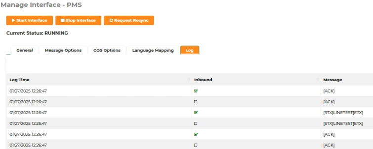
To begin testing the physical com port labelled PMS you can follow these steps
- Navigate to Guest Management > Interfaces - PMS and stop the PMS interface
- Connect a db9 loopback connector or short pins 2 and 3 with a metal object such as a paperclip to loop the transmit and receive pins 2 and 3 together right at PMS port on teh comxchange controller.
- With the pins connected, now start the PMS interface again. You should see any outbound messages that are transmitted loop back and be received by the ComXchange server. Thi sis indicated by identical message pairs, once of which shows a green check mark in the inbound column.
- You can also use a db9 mini tester to verify that the pins have some power and that they blink as data is transmitted and received
- Start the PMS interface
- Open the PMS interface log tab
- Look for any outbound messages noted with an empty check box in the "Inbound" column to be repeated as an inbound message which will have the "Inbound" check box marked
- When testing with the default Comxchange emulation settings you should see an ACK and a LineTest Message when the interface is started
![]()
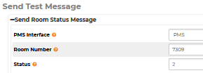
- You can also send a status message by clicking on the Test Room Status button either from the main interfaces page or from the flyout menu on the right while in the interfaces page. Choose a guest room number and assign a status such as 2
- You should see an outbound sts 2 message followed by an inbound sts 2 message

Test the Cable
If tests from the serial port work you can connect the serial cable and test on the far end of the cable that will be connected to the PMS serial connection and either connect the db9 loopback or short pins 2 and 3 to create a loopback. You can also connect to a a PC running a PMS simulator to verify the ComXchange will reply to inbound messages
Cable Loopback Test
- Navigate to Guest Management > Interfaces - PMS and stop the PMS interface briefly then restart it
- Open the PMS interface log tab
- Look for outbound messages to be repeated as inbound messages.
- If this is unsuccessful, retry at each cable junction (if any) starting at the comxchange again. Add in one cable segment at a time, moving further from the comxchange and closer to the PMS equipment with each test until the test fails. When the test fails, segment between this failed test the prior successful test will be your problem cable and should be replaced. Continue replacing segments and retesting until teh entire cable length will successfully perfom a loopback test. There is no quick way to do this, no shortcut. Test each cable segment in turn until all bad segments are found / replaced and the loopback test succeeds at the point where you would connecto the PMS equipment.
- If you cannot get a loopback at the PMS equipment and all cable segments are thought to be good, it may be because the total length exceeds the limit of 50 ft.
PMS Simulator Test
- Connect the serial cable from the ComXchange PMS com port to a PC with a built in Serial port or a USB to serial cable and a PMS simulator
- Click on the file tab and open a new interface, set the type to Hitachi PMS.
- Open the Com Settings and set them to match the com settings on the ComXchange 9600, 8,none, and 1 by default
- You can Start and stop the interface and if the message options are set as default you should see the ComXchange send an ENQ, the simulator should reply with an ACK and then the ComXchange will send a Line Test, then receive another ACK,
If you are set with the Fosse message options disabled you can still test, there will be no line test but you can send a ENQ or a Check In / Out from the PMS simulator and you should see the ComXchange Reply with an ACK.
You can also send a test room status from the interfaces page or flyout menu to have the ComXchange initiate a message and the Simulator should reply with an ACK.
If you have a mini tester you should see the transmit and receive lights lit up and blinking when data is sent over the serial connection.
IP / IP to serial Testing
To test an IP Interface connection without directly connecting to the PMS you can use an IP to serial device and a PMS simulator.
- Connect the serial port of the IP to serial device to a PC built in or USB to serial connection with a PMS simulator on the PC
- Match the serial settings of the simulator and the serial connection on the IP to serial device. See above, testing with a PMS simulator
- Set the ComXchange PMS interface to use the ComXchange emulation
- Set IP Enabled to Yes
- Match the IP address of the IP to serial device and choose a port to talk to the IP to serial device on
- Set the IP interface to talk to the ComXchange IP address and port on the IP to serial device
- The IP to serial device should be set up as a server (the ComXchange acts as a client)
In some IP to serial devices you will see that
the ethernet connection status is connected and if the interface is running you should begin to see the Transmit and Receive count go up.
Once Traffic is flowing on the IP side you should be able to verify with status lights on the IP to serial device or using a db9 mini tester that the data is being transmitted and received over the serial side of the device. The PMS simulator should then be receiving messages from and be able to send messages to The ComXchange PMS interface which will be viewable from the PMS Interface log tab. Once you can verify that data is being sent from the PMS server and received by a simulator you can be fairly certain that the handoff from the ComXchange should work when connected to the PMS server's port. When you connect to the PMS and are not seeing any data you should try a null modem to swap the transmit and receive pins and retest to see if the PMS can then receive and transmit data to the ComXchange. If communication still fails and all the testing above has been successful The PMS provider will need to troubleshoot any physical and software on the PMS server.
CAS (CAll Accounting Server) PMS Interface Testing
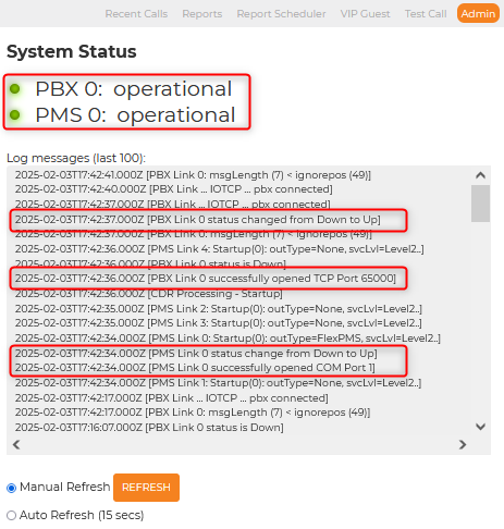
The Call Accounting server also has a PMS interface that can connect to and send chargeable call records to the PMS. For more information about the call accounting interfaces see the interfaces section of the Call Accounting wiki. To test the Call Accounting Server interface you can do similar tests to verify the serial port that is labeled CAS, and cables are good to transmit and receive data and after verifying the physical connections you can test the the Call Accounting software by posting a test call out the call accounting PMS interface and monitoring it with the Call Accounting data monitor. When you navigate to the Admin tab of the Call Accounting server you should see both interfaces as Operational and see information from the log file showing the interface links as successfully opened and a status of Up. Testing the Physical port and cables
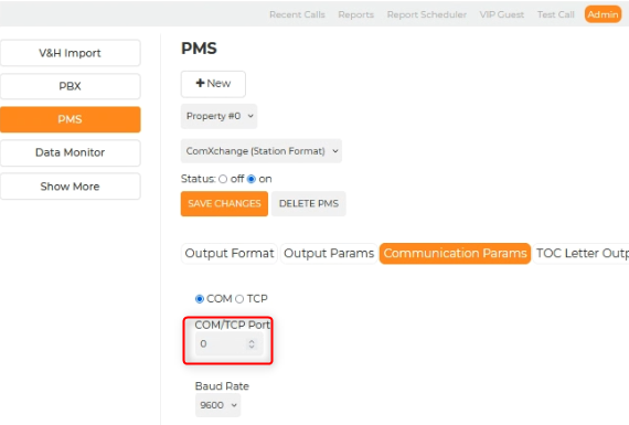
You can use a mintester to see if there is data on the Transmit and Receive pins. However, You may find that testing and verifying the physical port labeled CAS and cabling is easier when using the ComXchange PMS interface. The test messages are simpler to verify that you have a loopback, and that data can be transmitted and received over the physical port and cables. To do this you can switch the com ports being used between the two interfaces. Below is an example of swapping the com ports that the PMS and Call Accounting are using for testing purposes. When testing the physical connection is done you will need to swap the com ports back to their original configuration.
Navigate to Reports > Call Accounting to open the Call Accounting server GUI
Navigate to Admin > PMS - Communication Parameters tab
Change the com port from 1 to 0
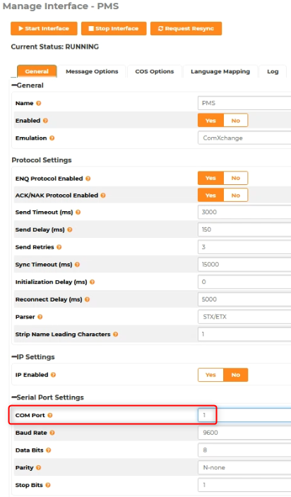
Navigate the ComXchange Admin GUI Guest Management > interfaces - PMS
Change the com port from 0 to 1
This will allow us to use the PMS interface and logs to verify the serial port labeled CAS or com port 1 can send and receive data
Follow the steps above for testing the
com port and cabling but this time using the physical port labelled CAS. When finished verifying the physical port and cable is working you can set the Call Accounting (PMS) interface back to use com port 1 (physical port labelled CAS) and the ComXchange PMS interface back to use comport 0 (physical port labelled PMS)
You can then test the call accounting software by connecting the serial port labelled CAS to a PC
Testing Call Accounting Server to PMS Records
If you are having trouble with the PMS not receiving records or they are not ready for a connection and you want to verify that a chargeable record will be sent out the Call Accounting PMS interface you can use the built in Test Call and Data Monitor features and a PMS simulator to verify a call that should be charged to a room will be posted. Note that with the default settings the Call Accounting server will expect and ACK to an ENQ message before sending the call record data out the interface.
- Connect the serial cable from the ComXchange CAS com port to a PC with a built in Serial port or a USB to serial cable and a PMS simulator
- Click on the file tab and open a new interface, you can use the Hitachi PMS option
- Open the Com Settings and set them to match the Call Accounting com settings on the ComXchange 1200, 8,none, and 1 by default
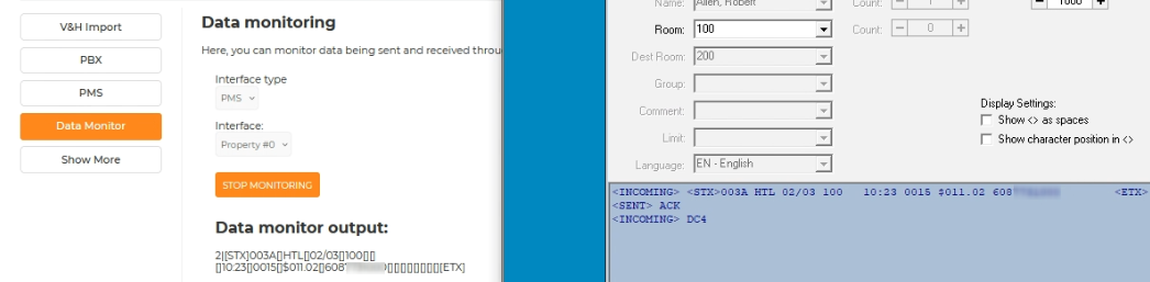
- Open a tab and navigate to Reports > Call Accounting > Admin - Data Monitor
- Choose the PMS interface type in the drop down and click on Start monitoring
- Click on the link for more information on the Data Monitor
- Open a second tab and navigate to Reports > Call Accounting > Test Call
- Fill in the test call information for a call that should be long distance from the hotel and check the "Post to PMS" check box Click on submit
- Click on the link for more information on Creating a Test Call
- You should see output in the Data monitor output and an incoming call record in the PMS simulator with the room number, called number, and date information
If you have a mini tester you should see the transmit and receive lights lit up and blinking when data is sent over the serial connection. Once you can verify that data is being sent from the Call Accounting server and received by a simulator you can be fairly certain that the handoff from the ComXchange should work when connected to the Call Accounting PMS port. When you connect the CAS port to the PMS and are not seeing any data you should try a null modem to swap the transmit and receive pins and retest to see if the PMS can then receive and transmit data to the ComXchange. If communication still fails and all the testing above has been successful The PMS provider will need to troubleshoot any physical and software on the PMS server.
 Uploading ....